How to Perform System Diagnostics with a FUELAB 529xx Series Fuel Pressure Regulator
This article is a continuation of the FUELAB article, How FUELAB's Electronic Regulators Work, which describes the function of the FUELAB 529xx Series Electronic Fuel Pressure Regulator. We recommend reading that article before moving onto this article, which discusses how to perform diagnostics on the Electronic Regulator when used with a FUELAB Fuel System, as well as how to measure and track the regulator’s Analog Output to determine the general heath of the fuel system. 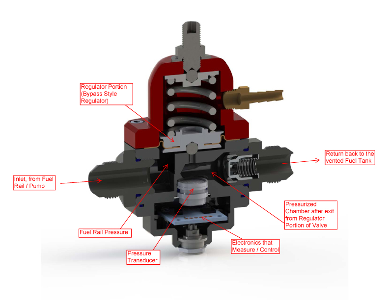
Figure 1 - Cross Section View of FUELAB 529xx Series Electronic Regulator Regulator Operation Summary: As described in our previous article, the 529xx series regulator is a bypass style mechanical regulator, and fuel pressure is maintained at the fuel rail using the same method of operation as all bypass style regulators; the flow rate in excess of what the engine consumes is returned to the fuel tank. However, the 529xx regulator performs the additional function of controlling fuel pump speed to match fuel demand; thereby keeping fuel cooler, and fuel pressure more stable. By sensing the amount of fuel being returned to the fuel tank, the regulator signals the pump to slow down when the return flow rate is high, and when the return rate is low it signals the pump to speed up. Thus, maintaining a constant return line flow rate and the correct fuel rail pressure.
Measurement of return line flow rate: To determine the fuel return flow rate, the regulator uses a pressure transducer to measure the amount of pressure created by a relief valve in the return line. The set target pressure (about 12PSIG) for the transducer is enough to maintain a flow rate of about 40GPH to 50GPH through the return line. By measuring at this location, instead of measuring the rail pressure directly, the regulator is able to measure fluctuations in demand with greater sensitivity. Thus, small changes in fuel demand, which equate to very small changes if measured at the fuel rail, can be measured more accurately. The regulator processes the information from the pressure readings to calculate the proper speed at which the pump must operate to maintain balance.
Bypassing the electronic regulator: While there should be no reason (other than possible diagnostics of the system) to operate the regulator as a standard bypass regulator, it is possible to perform this function. If the relief valve assembly that is used for the electronic regulator (see Figure 1) was replaced with a standard AN fitting (no relief valve in the fuel return line), the amount of return line back pressure normally present would be absent. The pressure transducer would read this loss of pressure as an increase in demand, and signal the pump to increase speed. The system would quickly go to full speed, as the pressure reading would remain low, and thus instruct the fuel pump to remain at full speed. How the regulator communicates with the fuel pump, PWM Output Signal (White Wire):
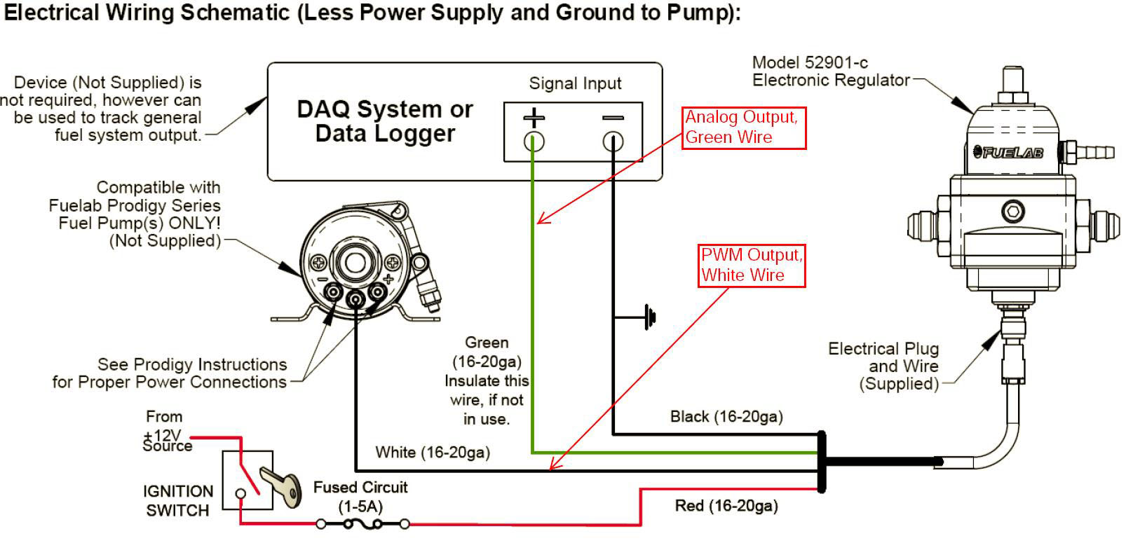
Figure 2: Wiring Diagram for the Electronic Regulator While power and ground connections are relatively simple to understand, the two output signals from the regulator have a more complex action. The speed control wire (white) has a PWM (Pulse Width Modulated) signal, generated by the regulator. This signal communicates to the Fuelab Prodigy Fuel Pump, exactly what speed to operate at. As shown in Figures 3 and 4, the PWM signal is simply a voltage that goes between high and low very quickly over time. When the regulator senses that fuel demand is higher than what the pump is supplying, it increases the percentage of time the PWM signal is high vs. low to increase pump speed. The percentage of time that the signal is high vs. low is called the Duty Cycle (much like the action of a fuel injector, except it is not carrying an electrical load, just a very low current signal).
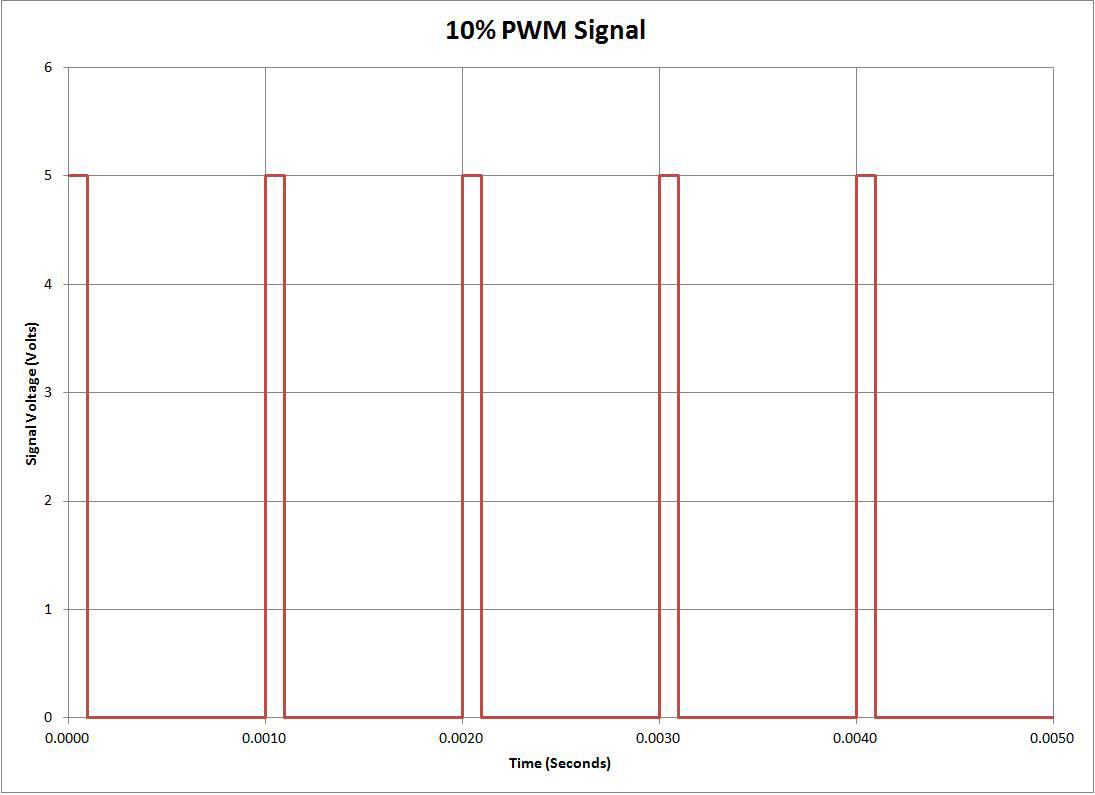
Figure 3: PWM Signal at 10% Duty Cycle

Figure 4: PWM Signal at 90% Duty Cycle Typically, the minimum speed signal the electronic regulator will send is a PWM signal at 30% Duty Cycle. An example of this PWM Signal is shown below, in Figure 5.
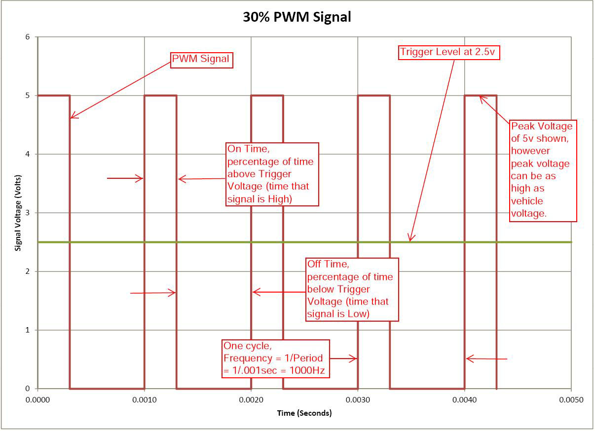
Figure 5: PWM Signal at 30% Duty Cycle Note in Figure 5, that the signal frequency, in this case at 1000Hz (one thousand times in a second), remains constant no matter what Dwell Time Percentage. Of note, the Prodigy Series Fuel Pump recognizes PWM frequencies between 500Hz and 1500Hz, between 10% and 90% Duty Cycles. The advantage of this type of signal is that the value it transmits (the "modulated signal", in this case: Dwell Time) is independent of voltage. It should be noted that while the examples displayed in Figure 2 through Figure 5 show the voltage peak of the "Square Wave" to be 5 volts, which is the voltage peak of the 529xx series regulator, the Prodigy Pump is capable of reading peak signal voltage ranging from about 3 Volts to 20 Volts.
Analog Output Signal (Green Wire): While it is possible to capture and use the PWM signal as a means for diagnostics, the interpretation can be cumbersome. This is when the Analog Output (Green) Wire can come in handy. The output is a 0v to 5v signal that is proportional to the output speed signal of the regulator. Typically, the output during engine idle is at about 1.4v (representing close to 30% PWM signal), while output at full speed is about 4.5v (representing close to 90% PWM signal). This signal (Voltage) can be measured directly using a simple multimeter. Some FUELAB customers send this signal directly to their Data Logging System or ECU, giving them the ability to track consistency of fuel delivery as well as the total capacity of the fuel system during operation.

Figure 6: Voltmeter with Bar Graph Some voltmeters display a bar graph, as shown in Figure 6, which can be helpful for observing fast changes or fluctuations in the readings. Fast changes or oscillations can occur when the fuel system is plumbed improperly. Bar graph readings can make these fluctuations more obvious than digital readings.
Summary: In summary, by measuring and tracking the Analog Output of the regulator, the general heath of the fuel system can be monitored. By collecting and analyzing data from the regulator, abnormal regulator operation can be detected as well. This functionality can be useful for quick onsite evaluation; Fuel flow capacity can be assessed between races, even showing such problems as filters that are becoming blocked - well before they create symptoms of fuel pressure loss.
Future Article: In a future article we will present additional examples of how the FUELAB 529xx Series Electronic Fuel Pressure Regulator is used to for fuel system diagnostics.
You must login to post comments.