How to Perform System Diagnostics with a FUELAB 529xx Series Fuel Pressure Regulator: Part 2
This article is a continuation of the FUELAB article, How to Perform System Diagnostics with a FUELAB 529xx Series Regulator, that discussed how to perform diagnostics on the FUELAB 529xx Series Electronic Fuel Pressure Regulator when used with a FUELAB Fuel System, as well as how to measure and track the regulator’s Analog Output to determine the general heath of the fuel system. Also, that article contains links to more basic information on FUELAB Electronic Regulator function. We recommend reading that article before moving onto this article, which presents expands on points made in that article, as well as describes what can cause the problems detected during Analog Output analyzation.
Issues Created by Improper Fuel Line Plumbing Fast Changes and Oscillation in Fuel Pump Speed The previous diagnostics article briefly touched on how a voltmeter can be used to analyze the analog output wire to detect fast changes or oscillations in fuel pump speed that can occur when the fuel system is plumbed improperly. Note that while oscillation can be detected with a volt meter, changes in fuel pump speed can also be heard. We’ll now expand on what can cause these changes or oscillation. Severe Oscillation Symptoms Oscillation can occur when the system is out of balance or is not being used as intended. It should be noted that normal responses during system operation using a FUELAB electronic regulator can create variation and temporary oscillation, and that FUELAB electronic regulators use a unique method of control that can contribute to responses in demand that may sound out of sync of actual engine demand. As long as oscillation is not continuous, then the responses are considered normal. However, continuous fast changes or oscillation in pump speed can indicate fuel line plumbing problems. Air Entrainment within the Fuel Tank Air entrainment in the fuel tank can be created by improper fuel line plumbing. It is important, especially with use of an electronic regulator, the fuel returned to the fuel tank exits below the surface of the fuel (as exemplified by Figure 1). If it is above the fluid surface (as shown in Figure 2), it can draw in air, and when pockets of air enter the fuel pump the pumping efficiency will lower. This action results in a loss of flow rate that is responded to by the regulator with a command to increase speed. Rapid changes in the amounts of air induced will cause quick changes in pump speed. This FUELAB video demonstrates the effects of a return line that stirs in air: https://www.youtube.com/watch?v=dP6Pogm6Ts0 Figure 1 - Return Line Exiting Below Surface 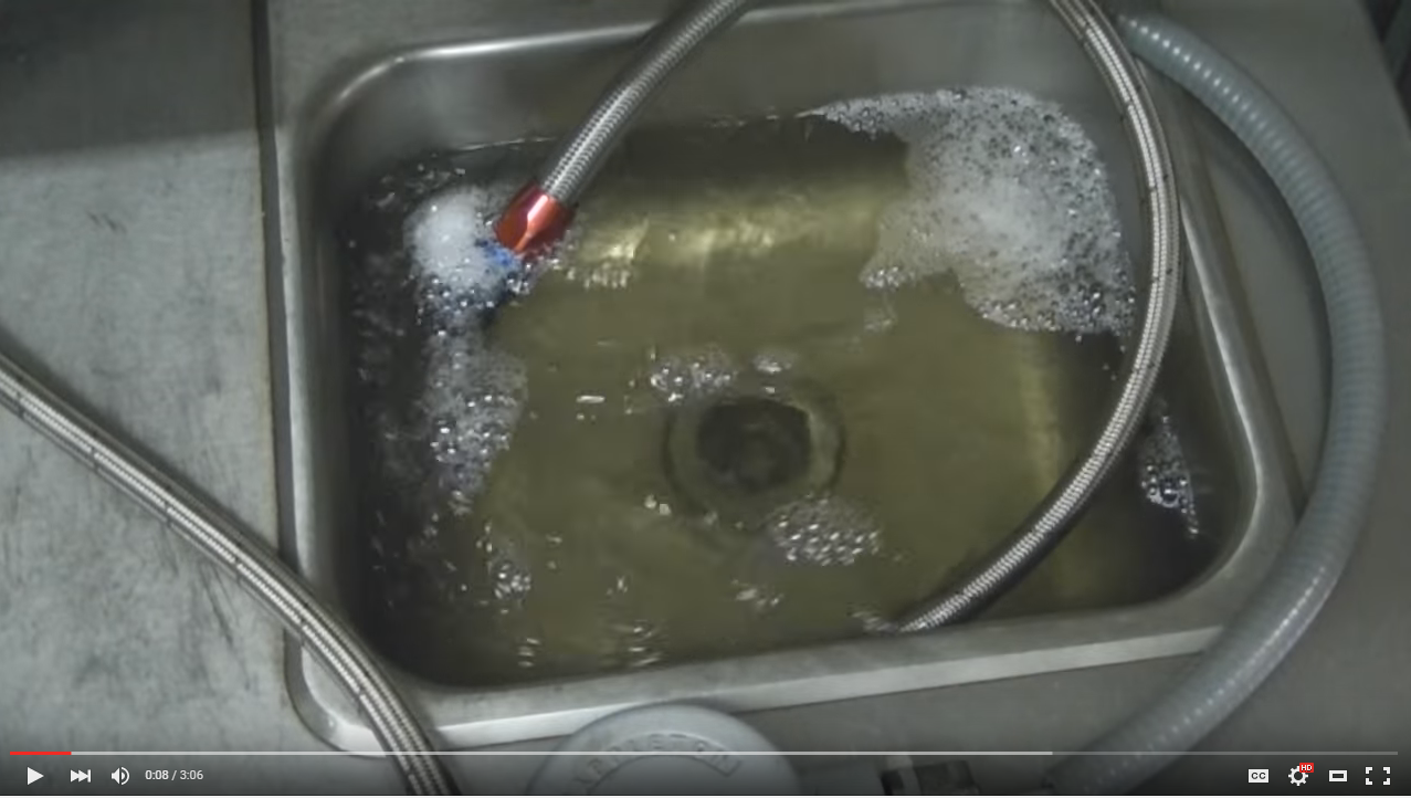 Figure 2 - Return Line Exiting Above Surface
 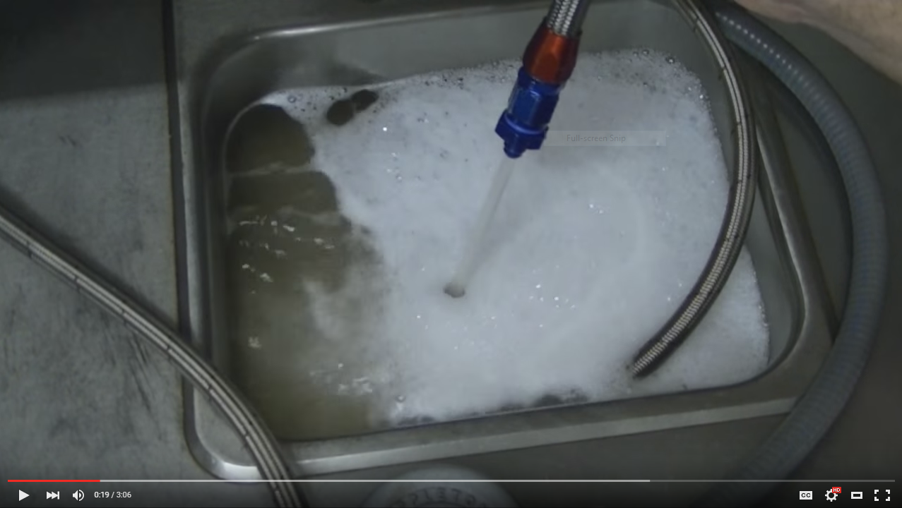 Rapid Change and Oscillation Caused by System Over-Response Every system of control inherently can be vulnerable to oscillation and error. It is inherent, as the system only responds to error or possible anticipation of error. The amount of error measured or found by the electronic regulator will be matched with a proportional amount of change to fuel pump speed. The more error that is found, the bigger the change in the system will occur. To have a quicker response, a larger gain can be employed, however as can be imagined, when gains get too high, responses can be too much. When this happens, a system can wildly oscillate. This can be compounded with variation of plumbing lengths and sizes. PID Control Helps Reduce Fast Changes and Oscillation FUELAB electronic regulators use PID control to buffer system reactions, and thereby lessen fast changes and oscillation. In general, covering the topic of PID (proportional, integral and derivative) is time consuming, but relevant as a general description of the method that the regulator operates with, regarding the amount of correction the regulator responds with. While the terms of integral and derivative in PID are significant regarding control, the proportional term can be more readily and easily explained. This means simply the amount of error measured by the regulator will be matched with a proportional amount of change. As described above, when gains get too high, regulator responses can be too much. Therefore, much more conservative settings must be applied: To have greater response in one direction, a slower response in the opposite direction is employed. In other words, for the regulator to respond to a sudden increase in engine demand (detected too low of pressure at the transducer), the regulator's response to a loss of demand (detected too high of pressure) is slowed down. FUELAB’s electronic regulators maintain stability over a wide range of operating conditions by controlling their rate of response, as too fast a response can send the system into violent oscillations, while too slow of a response can lead to an engine lean out during sudden engine throttle up and vehicle acceleration. By maintaining fuel rail pressure with a relief valve (the bypass style regulator), extra fuel flow can be returned back to the fuel tank, and at a high rate when needed. Therefore, speeding up the fuel pump is more important to maintaining pressure than slowing the pump down. When the regulator detects that demand is increasing (pressure transducer readings are below the target pressure), the regulator responds with a fast increase in fuel pump speed. To dampen any overshoot in flow rate (in response from readings above the target pressure), the regulator responds with a slow decrease in speed sent to the fuel pump. This characteristic can be heard during every startup of the fuel system. Each time the system is turned on, the regulator instantly reads the system as needing a dramatic increase in pump speed. The pump can be heard going to full speed during starting. Once the system is pressurized, the pump can be heard slowing down at a reduced rate. Return Line Pressurization Can Cause Issues One limitation the 529xx Series Regulator has is that the pressure transducer (used to measure relief valve pressure) is referenced to the atmosphere, or gauge pressure instead of being deferentially measured. This means that the return line must be returned to a vented fuel cell or tank. If a reservoir or surge tank is used, the tank can become pressurized and throw off readings. Excessive restriction in the return line or use of a pressurized tank can result in an unstable operating condition, or force the system to operate at minimum speed. For pressurized reservoir or surge tank usage, the return line must be returned back to the main fuel cell or tank that is vented. To rule out problems caused by a return line when performing diagnostics, a temporary line can be plumbed from the return line on the regulator into a fuel safe container. If operation of the system becomes stable then the return line on the vehicle must be analyzed.
Response to Change in Fuel Flow Rate In our previous electronic regulator diagnostics article we discussed how the FUELAB regulator measures return line flow rate using a pressure transducer to read the amount of pressure created by a relief valve in the return line. It was described that by measuring at this location, instead of measuring the rail pressure directly, the regulator is able to measure fluctuations in demand with greater sensitivity. Thus, small changes in fuel demand, which equate to very small changes if measured at the fuel rail, can be measured more accurately. To show the difference in measurement of changes in rail pressure vs. changes in the regulator's transducer readings, a test was conducted with results shown in figure 3. Five sets of measurements were taken, including the regulator's transducer output and the rail pressure transducer output, while manually changing pump speed (thus overriding the regulator's commands). To compare the readings of the two different pressure gauges (transducers), both ranges are represented in their respective 5 Volt output ranges (approximately 0-15 psi for the regulator's transducer labeled TO, in red and 0-85 psi for the rail pressure transducer labeled OP, in blue). The flow rate shown represents the system operating at near 100% of capacity at 0 flow through the regulator, to 100 representing nearly all of the flow going through the regulator, such as at idle condition. Figure 3 - Response to Change in Flow Rate 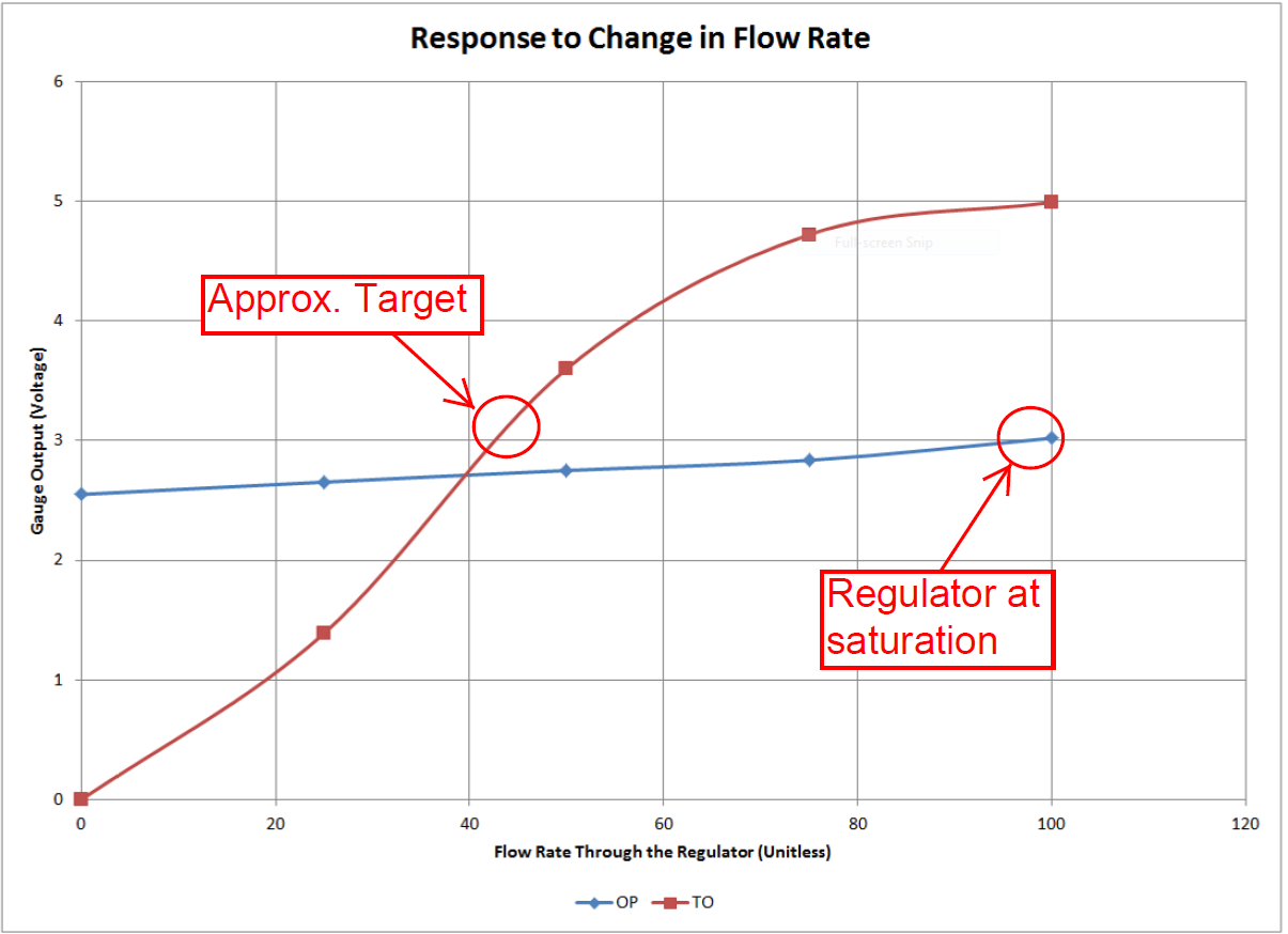 When examining the rail pressure (blue line), the regulator response is shown to be normal and predictable. This flat line has a slight linear slope, in response to the different flow rates. As can be seen, the regulator is doing its job in holding the pressure constant. As documented in previous articles, every bypass style regulator exhibits this characteristic - referred to as the Pressure Regulation Slope. While the rail pressure is shown to vary a small amount (less than 1/2 Volt in range), the regulator's pressure transducer output (the red line labeled TO) varies the entire 5 Volt range. This allows for pronounced measurement of changes in demand, and gives the regulator much greater sensitivity when measuring change in flow, versus observing rail pressure alone. As shown in figure 3, a location is noted "Regulator at saturation". Due to the pressure drop at the relief valve, the electronic regulator has a diminished capacity at high flow rates when compared to the standard bypass regulator. However, when operating normally, the operating conditions are not in this region - even with two high flow Prodigy fuel pumps in the system. This allows the system to operate two pumps (that can total up to 380+ GPH in capacity) with a return line as small as a -6AN (3/8"). Normally this would require a -8AN (1/2") or -10AN (5/8") size return line. It is important to note that use of the electronic regulator strictly as a bypass valve will have diminished capacity. This concludes our article on performing system diagnostics with a FUELAB 529xx Series Regulator. As always, if there are issues encountered using a FUELAB product or questions regarding usage, please contact us.
You must login to post comments.