Fuel Pressure Regulators - Low Pressure Applications
Introduction Low pressure automotive fuel delivery systems were the norm decades ago, with fuel being fed to a carburetor by a low pressure fuel pump (1-3 psi). These lower pressure carbureted systems historically came from gravity fed systems. As time went by, most carbureted systems increased fuel pressure, and even higher pressures came into play with the advent and proliferation of fuel injection. It seems that low pressure systems have all but been forgotten, and their components often ignored in the automotive aftermarket. However, low pressure fuel systems do remain in use today, and are still very relevant. For example vintage cars fitted with SK, Weber or Stromberg carburetors. Aftermarket high performance low pressure fuel pumps and fuel pressure regulators sometimes replace OE parts for better performance and reliability, and in some cases aftermarket pressure regulators may be implemented where a regulator wasn’t previously used. This article will focus on the types of low pressure fuel pressure regulators offered by FUELAB; bypass style (aka: return style) and blocking style (aka: traditional style), how they function, and the benefits and drawbacks of each style as they apply to low pressure applications (1-4 psi). We will then go over specific FUELAB low pressure regulator models, describe their specifications, and describe what system requirements need to be in place for their use.
Fuel Pressure Regulator Styles Let’s discuss the design and operation of blocking and traditional style fuel pressure regulators. Blocking Style Fuel Pressure Regulators (aka: Traditional Style) Below is an example of a FUELAB blocking style fuel pressure regulator. Please note the cut-away image shows the fuel regulator in the valve open position. 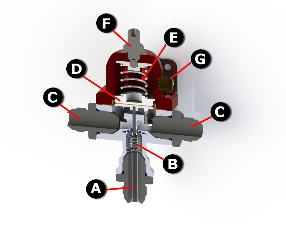 Design With a blocking style regulator, fuel enters through the inlet port (A) and travels past the fuel control valve (B) and then is distributed through an outlet port to the carburetor. In this example, there are two outlet ports (C). Fuel flow and pressure are controlled by the fuel control valve that is actuated by a diaphragm (D). The diaphragms movement up and down is limited by a spring (E). Fuel pressure (psi) to the carburetor is set with a threaded adjustment mechanism (F). A vacuum/boost reference port allows the regulator to compensate for boost pressure with forced induction applications (G). Blocking style regulators are characterized by their lack of a fuel return line from the regulator back to the fuel tank.
Operation Fuel travels into the regulator and flows out to the carburetor. Fuel line pressure is high from the fuel pump to the regulator, and then less from the regulator to the carburetor. As fuel pressure in the carburetor float bowls increases, so does pressure within the regulator, causing fuel to push upward against the diaphragm. As fuel pressure increases, the diaphragm moves upward, and the fuel control valve progressively reduces fuel flow and pressure as it is moved toward a closed position. When the fuel pressure reaches the maximum pressure to which the regulator has been set (this pressure setting is usually based on the maximum which the carburetor manufacturer has specified will provide optimal performance for the carburetor), the diaphragm has pushed upward to where it has closed the fuel control valve. As the engine demands fuel from the carburetor, the float bowls begin to empty and this causes fuel line pressure to drop. As line pressure drops the regulator diaphragm descends, which progressively opens the fuel control valve, increasing fuel flow and line pressure. By using the threaded adjustment mechanism to increase tension on the diaphragm spring, it becomes harder for pressurized fuel to push the diaphragm upward; more fuel pressure must build to push the diaphragm. Thus, increasing tension on the diaphragm spring with the threaded adjustment mechanism is how the regulator is set to increase fuel pressure to the carburetor. Conversely, decreasing spring tension sets fuel pressure lower. Also to be taken into consideration for blow-through turbocharged or supercharged applications is the function of the vacuum/boost reference port. When under boost, compressed air from the turbo (or supercharger) is blown through the carburetor, which pressurizes the carburetor and the float chambers. Fuel being fed to the carburetor will encounter resistance from this pressurization. For example, let’s say a carburetor requires 8 psi of fuel pressure and the engine is currently being delivered 7 psi of boost pressure. The carburetor is now under 7 psi of boost pressure which is resisting the 8 psi of fuel pressure being delivered from the regulator. That means 7 psi of the fuel pressure delivered to the carburetor must be used to overcome resistance, netting only 1 psi being delivered to the carburetor. This can allow the float chambers to run dry, and interrupt fuel flow to the engine. In order for the carburetor to deliver 8 psi to the engine, the regulator needs to provide an additional 7 psi to overcome resistance. That means a total of 15 psi of fuel line pressure must be allowed by the regulator. However, the diaphragm has been set to move the fuel control valve to the closed position once line pressure of 8 psi has been reached. This is where the vacuum/boost reference tube comes into play. A boost reference line is run from the carburetor box, or hat, to the vacuum/boost reference port. As boost pressurizes the carburetor, the same amount of pressure is applied to the boost reference line, which pressurizes the diaphragm housing of the regulator. This pressure is applied to the top side of diaphragm so that it becomes more difficult for fuel line pressure to move it upward. Thus working together with the diaphragm spring to allow more fuel pressure (8 psi spring + 7 psi assistance = 15 psi). Boost reference enables fuel pressure to be raised 1:1 with boost pressure – overcoming the rising air pressure and making certain the float chambers remain properly filled.
The advantages of the blocking style regulator
- - Requires no fuel return line and fittings from the regulator to the fuel tank. Reducing weight, complexity (routing a return line can prove to be difficult), and expense. It should be noted that a blocking style regulator does need an internal or external relief valve at the fuel pump; relieving bypassed fuel and pressure to the fuel tank.
- - Multiple regulators (set at different pressures, such as with a nitrous oxide system application) may be used from one pump
The disadvantages of the blocking style regulator
- - As fuel pressure reaches the maximum value to which the regulator has been set, the internal valve must shut off inlet pressure from getting to the outlet side of the valve. This action requires extra force (fuel pressure) to fully shut the valve off and creates a spike in fuel pressure as the valve reaches the closed position. The result is a slightly higher outlet pressure that could over-pressurize the carburetor and overfill the float bowls. The graph below demonstrates this condition.

- - In the closed position, leakage of the fuel control valve can cause fuel pressure to continue to build at the outlet. This is termed as "pressure creep". This too can over-pressurize the carburetor and overfill the float bowls.
- - The fuel control valve of blocking style regulators is more sensitive to debris that can keep it from completely closing – thereby causing pressure creep
- - Often, fuel pressure readings with the fuel control valve fully closed and the engine shut off (but with the fuel pump energized) can be inconsistent. Meaning that the engine can be run and shut off multiple times, and pressure readings taken between each run/shut off cycle off can vary. For this reason, pressure adjustments for blocking style regulators should be adjusted while the engine is idling, to keep a small amount of fuel always running through the regulator for greater consistency.
- - It should be noted that blocking regulators may not be a good choice for blow though forced induction systems as the inherent design of the fuel control valve can create a significant fuel pressure differentiation between the inlet and outlet (higher at the inlet, lower at the outlet). However, this issue applies to applications requiring high fuel flow and fuel pressure, and does not pose problems with the low flow/pressure applications covered by this article.
Bypass Style Fuel Pressure Regulators (aka: Return Style) Below is an example of a FUELAB bypass style fuel pressure regulator. Please note the cut-away image shows the fuel regulator in the valve closed position.
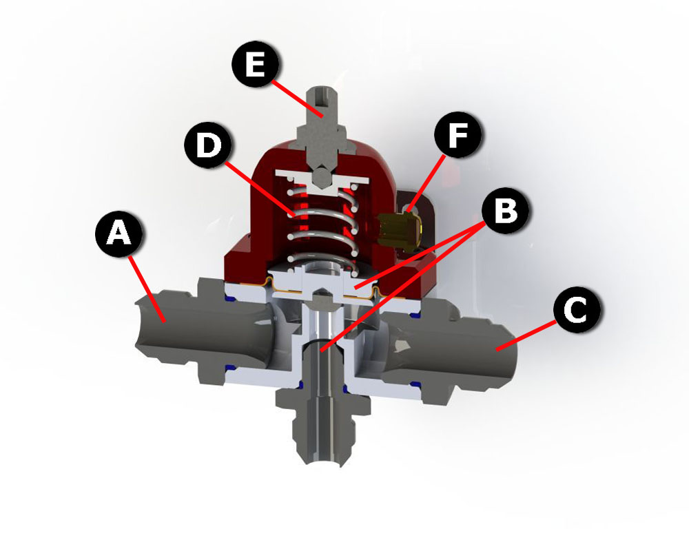 Design With a bypass style regulator, fuel enters through the inlet port (A) and travels past a fuel bypass valve/fuel return line port (which governs fuel flow and pressure) (B) and then is distributed through an outlet port to the carburetor (C). Opening and closing of the bypass valve is limited by a spring (D). Fuel pressure (psi) to the carburetor is set with a threaded adjustment mechanism (E). A vacuum/boost reference port allows the regulator to compensate for boost pressure with forced induction applications (F). Bypass style regulators are characterized by a fuel return line from the regulator back to the fuel tank. Operation Fuel travels into the regulator and flows out to the carburetor. As fuel pressure in the carburetor float bowls increases, so does pressure within the regulator, causing fuel to push upward against the fuel bypass valve. As the fuel pressure reaches the maximum pressure to which the regulator has been set (this pressure setting is usually based on the maximum which the carburetor manufacturer has specified will provide optimal performance for the carburetor), the fuel bypass valve is progressively pushed open to bleed off fuel flow and pressure. This fuel is sent back to the fuel tank via a return fuel line. As the engine demands fuel from the carburetor, the float chambers begin to empty causing fuel line pressure to drop. As line pressure drops the fuel bypass valve descends, progressively closing it off, thereby increasing fuel flow and line pressure. By using the threaded adjustment mechanism to increase tension on the fuel bypass valve, it becomes harder for pressurized fuel to push the valve upward; more fuel pressure must build to push it open. Thus, increasing tension on the bypass valve spring with the threaded adjustment mechanism is how the regulator is set to increase fuel pressure to the carburetor. Conversely, decreasing spring tension sets fuel pressure lower. The vacuum/boost reference port operates in the same fashion as the blocking style regulator.
The advantages of the bypass style regulator
- - Return style provides constant effective fuel pressure to the outlet port - pressure overage is bled off through the return port as needed.
- - Constant effective fuel pressure enables fuel pressure to be set more accurately, and should remain constant regardless of load. It should be noted that the engine is not required to operate to accurately adjust fuel pressure, however, the fuel pump does need to be energized.
- - Longer pump life and quieter pump operation as the pump is operating just hard enough to maintain pressure, instead of maintaining typically 10 to 20 PSI higher as is the case of blocking style regulators.
The disadvantages of the bypass style regulator
- - Added expense, complexity and weight of additional fuel lines and fittings
- - The return line is very sensitive to pressure drop, especially with these very low pressure ranges. Large return lines, 1/2" or higher, must be used with limited bends and direct return to unpressurized tanks or reservoirs.
- - Not applicable when multiple regulators need to be tied together (set at different pressures, such as with a nitrous oxide system use) and fed from one pump, as the entire fuel system will be limited by the regulator with the lowest pressure setting – negating those set to higher pressures
FUELAB Models and Applications FUELAB offers a range of blocking and bypass style fuel pressure regulators, with each designed and differentiated to meet specific fuel system layouts and requirements. All FUELAB low pressure fuel pressure regulators feature a fine thread pitch for precise pressure adjustment. They are also compatible with gasoline, diesel, methanol, and ethanol. All regulators are produced from billet aluminum with anodize per military standard MIL-A-8625, Type II, and feature versatile mounting brackets and stainless steel hardware. With regard to form, rather than function; please note a part number that includes "-c" means to substitute "-1" through "-6" for color reference, as these models of regulators can be available in 6 color schemes. 515XX Series & 525XX Series (Bypass Style) All 515XX Series and 525XX Series regulators accept port style and non-port style union fittings without interference. 515XX Series All 515XX Series regulators feature a return port located on the bottom of the regulator
Model Descriptions
- - Model 51505-c-L-L
- - 10AN Inlet Port and -10AN Outlet Port Size
- - 1-3 PSI
- - Large seat size
- Model 51506-c-L-L
- - 6AN Inlet Port and -6AN Outlet Port Sizes
- - 1-3 PSI
- - Large seat size
System requirements: 1/2" or larger return line required into vented fuel cell or tank for proper operation. 525XX Series All 525XX Series regulators feature an inline return and inlet port design for easy installation in extremely tight spaces
Model Description
- - Model 52503-c-L-L
- - 6AN Inlet with single -6AN Return, plumbed as a relief
- - 1-3 PSI
- - Large seat size
System requirements: 1/2" or larger return line required into vented fuel cell or tank for proper operation. 555XX Series (Blocking Style) All 555XX series regulators feature:
- - Aerospace poppet design fuel control valve for smooth regulating capability
- - Fuel control valve incorporates a “no creep soft seat” for positive sealing when closed. Avoids pressure creep
Model Description
- - Model 55502-c
- - 8AN Inlet Port with two -8AN Outlet Ports
- - 1-3 PSI
- - Large seat size
System requirements: Fuel Pump must have internal or external relief 575XX Series (Blocking Style – Miniature) All 575XX series regulators feature:
- - Aerospace poppet design fuel control valve for smooth regulating capability
- - Fuel control valve incorporates a “no creep soft seat” for positive sealing when closed. Avoids pressure creep
- - Reduced size to allow fit in tight locations
Model Descriptions
- - Model 57502-
- - 6AN Inlet Port with two -6AN Outlet Ports
- - 1-3 PSI
- - Large seat size
System requirements: Fuel Pump must have internal or external relief 585xx Series (Blocking style) The 585XX series regulator features:
- - Aerospace poppet design fuel control valve for smooth regulating capability
- - Fuel control valve incorporates a “no creep soft seat” for positive sealing when closed. Avoids pressure creep
- - The main seat assembly can be quickly exchanged in case of seat damage – such as debris. The seat assembly can be taken apart further to enable o-ring replacement of the Soft-Seat design.
- - Dual Inlet Ports, and four Outlet Ports – good for dual quad high flow carburetor set ups
- - 1.5” diaphragm assembly gives ability for extremely high flow rates with a flattened curve for pressure stability
Model Description
- - Model 58502-c
- - Dual -10AN Inlet Ports with four -6AN Outlet Ports
- - 2-4 PSI
System requirements: Fuel Pump must have internal or extern
You must login to post comments.